Electric motors turn electricity into motion by exploiting electromagnetic
induction. A current-carrying loop that is placed in a magnetic
field experiences a turning effect.A simple direct current (DC) motor
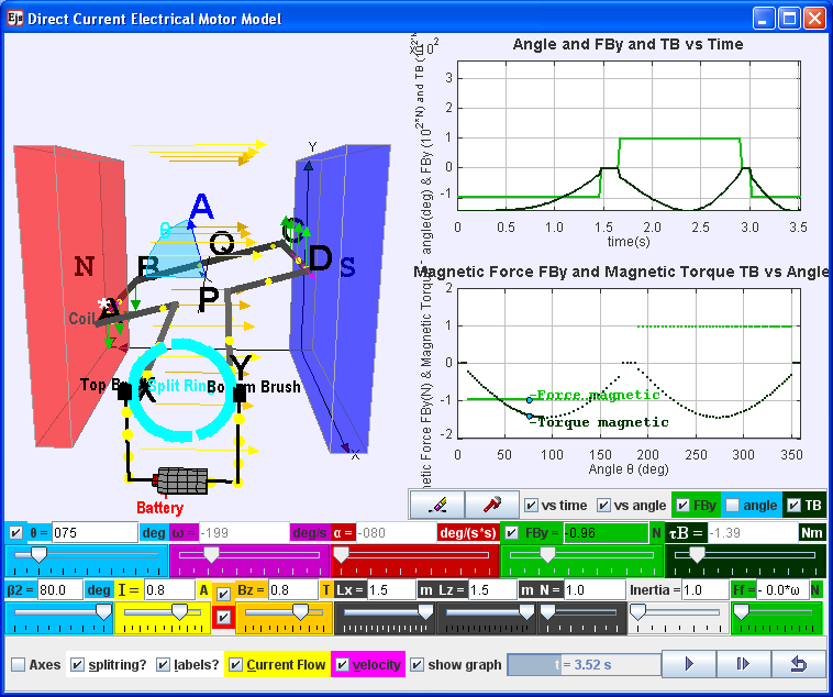
is illustrated here. ABCD is mounted on an axle PQ. The ends of the
wire are connected to a split ring commutator at position X & Y.
The commutator rotates with the loop. Two carbon brushes are made to
press lightly against the commutators.
The motor features a external magnet (called the stator because it’s fixed in place) and an turning coil of wire called an armature ( rotor or coil, because it rotates). The armature, carrying current provided by the battery, is an electromagnet, because a current-carrying wire generates a magnetic field; invisible magnetic field lines are circulating all around the wire of the armature.
The key to producing motion is positioning the electromagnet within the magnetic field of the permanent magnet (its field runs from its north to south poles). The armature experiences a force described by the left hand rule. This interplay of magnetic fields and moving charged particles (the electrons in the current) results in the magnetic force (depicted by the green arrows) that makes the armature spin because of the torque. Use the slider current I to see what happens when the flow of current is reversed. The checkbox current flow & electron flow alows different visualization since I = d(Q)/dt and Q= number of charge*e. The Play & Pause button allows freezing the 3D view for visualizing these forces, for checking for consistency with the left hand rule .
Description:
the following case describe a postive current i, postive B field, θ start (defined as angle between area vector of coil A and B field) = 90o , split-ring commutator gap β2= 80o
The split-ring commutator allows electricity
flows from the positive terminal of the battery through the circuit,
passes through a copper brush [rectangle black
boxes] to the commutator, then to the armature.
Postive current runs through ABCD as shown in the diagram (select
the checkbox labels?), a +y direction force would act on AB. An -y
direction force would act on CD. Taking moments about the axle
conveniently, reveals a resultant torque T = Fmag*AD*cosθ
acts on the coil loop. The coil loop rotates in an clockwise manner
(view from battery side) starting 90o until it
reaches the θ = 170o position (assuming that split ring
angle are default at β2 = 80o). At this θ = 170+o position,
the
current is cut off. However, the momentum of the loop carries it
past the horizontal position until the coil loop reaches θ = 190o
position. Contact between loop and split ring commutator
is established again and the current in the coil loop is now reversed
(note that current i is still positive). A -y direction force now acts
on AB while a +y direction force acts on CD. The rotation motion is
reinforced clockwise (view from battery side) as θ continues to rotate
from 190o to 350o. At this θ = 350+o position,
the
current is cut off. However, the momentum of the loop carries it
past the verticall position until the coil loop reaches θ = 10o
position. Contact between loop and split ring commutator
is established again and the current in the coil loop is now reversed
back to same as at θ = 90o. A a +y direction force would act
on AB. An -y direction force would act on CD and the loop reaches θ = 90o
. The cycle repeats after θ = 90o allowing the armature to
experience torque in the reinforced direction at the right time to keep
it spinning.
Function of split-ring commutator:
The purpose of the commutator is to reverses the direction of the
current in the loop ABCD for every half a cycle.
A swing back and fro motion (maybe θ = 90o increase to 270o and decrease back to 90o) is all you would get out of this motor if it weren't for the split-ring commutator — the circular metal device split into parts (shown here in teal with a gap of β2) that connects the armature to the circuit.
The Direct Current Electrical Motor Model was created by Fu-Kwun Hwang (original model found here http://www.phy.ntnu.edu.tw/ntnujava/index.php?topic=912.0) , heavily customized by Loo Kang WEE (newer model found here http://www.phy.ntnu.edu.tw/ntnujava/index.php?topic=1266.0) using the Easy Java Simulations (EJS) version 4.3.3.3 authoring and modeling tool. An applet version of this model is available on the NTNU website < http://www.phy.ntnu.edu.tw/ntnujava/ >.
You can examine and modify this compiled EJS model if you run the model (double click on the model's jar file), right-click within a plot, and select "Open EJS Model" from the pop-up menu. You must, of course, have EJS installed on your computer. Information about EJS is available at: <http://www.um.es/fem/Ejs/> and in the OSP comPADRE collection <http://www.compadre.org/OSP/>.