 |
| http://weelookang.blogspot.sg/2010/06/ejs-open-source-direct-current.html Ejs Open Source Direct Current Electrical Motor Model Java Applet ( DC Motor ) « on: October 23, 2009, 06:14:56 PM » posted from:Singapore,,Singapore author: fu-kwun hwang and lookang https://dl.dropboxusercontent.com/u/44365627/lookangEJSS/export/ejs_model_DCmotor10.jar https://dl.dropboxusercontent.com/u/44365627/lookangEJSworkspace/export/ejs_users_sgeducation_lookang_DCmotor10.jar |
26
April 2011 version for research purpose

26
April 2011 version with rotated axes to display external
magnetic field from right to left

17
April 2011 Sunday version with graphs of angle, force and
torque vs time and angle


« on: October 23, 2009, 06:14:56 PM » posted from:Singapore,,Singapore
Ejs Open Source DC Motor Model by Fu-Kwun Hwang and lookang
now March2010 added Torque, Inertia.
this is a derived work based on http://www.phy.ntnu.edu.tw/ntnujava/index.php?topic=912.0
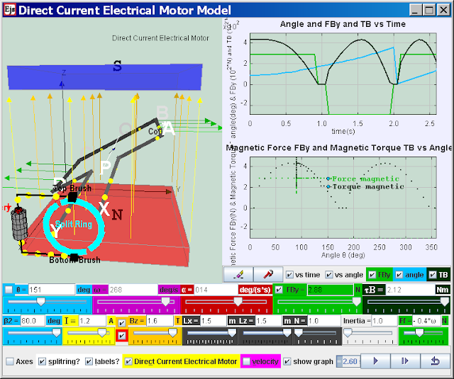
Direct Current Electrical Motor Model
Direct Current Electrical Motor Model
Electric motors turn electricity into motion by exploiting electromagnetic induction. A current-carrying loop that is placed in a magnetic field experiences a turning effect.A simple direct current (DC) motor is illustrated here. ABCD is mounted on an axle PQ. The ends of the wire are connected to a split ring commutator at position X & Y. The commutator rotates with the loop. Two carbon brushes are made to press lightly against the commutators.
The motor features a external magnet (called the stator because it’s fixed in place) and an turning coil of wire called an armature ( rotor or coil, because it rotates). The armature, carrying current provided by the battery, is an electromagnet, because a current-carrying wire generates a magnetic field; invisible magnetic field lines are circulating all around the wire of the armature.
The key to producing motion is positioning the electromagnet within the magnetic field of the permanent magnet (its field runs from its north to south poles). The armature experiences a force described by the left hand rule. This interplay of magnetic fields and moving charged particles (the electrons in the current) results in the magnetic force (depicted by the green arrows) that makes the armature spin because of the torque. Use the slider current I to see what happens when the flow of current is reversed. The checkbox current flow & electron flow alows different visualization since I = d(Q)/dt and Q= number of charge*e. The Play & Pause button allows freezing the 3D view for visualizing these forces, for checking for consistency with the left hand rule .
Description:
the following case describe a postive current i, postive B field, θ start = 90o , split-ring commutator gap β2= 80o
The split-ring commutator allows electricity flows from the positive terminal of the battery through the circuit, passes through a copper brush [rectangle black boxes] to the commutator, then to the armature.
Postive current runs through ABCD as shown in the diagram (select the checkbox labels?), a +y direction force would act on AB. An -y direction force would act on CD. Taking moments about the axle conveniently, reveals a resultant torque T = Fmag*AD*cosθ acts on the coil loop. The coil loop rotates in an clockwise manner (view from battery side) starting 90o until it reaches the θ = 170o position (assuming that split ring angle are default at β2 = 80o). At this θ = 170+o position, the current is cut off. However, the momentum of the loop carries it past the horizontal position until the coil loop reaches θ = 190o position. Contact between loop and split ring commutator is established again and the current in the coil loop is now reversed (note that current i is still positive). A -y direction force now acts on AB while a +y direction force acts on CD. The rotation motion is reinforced clockwise (view from battery side) as θ continues to rotate from 190o to 350o. At this θ = 350+o position, the current is cut off. However, the momentum of the loop carries it past the verticall position until the coil loop reaches θ = 10o position. Contact between loop and split ring commutator is established again and the current in the coil loop is now reversed back to same as at θ = 90o. A a +y direction force would act on AB. An -y direction force would act on CD and the loop reaches θ = 90o . The cycle repeats after θ = 90o allowing the armature to experience torque in the reinforced direction at the right time to keep it spinning.
Function of split-ring commutator:
The purpose of the commutator is to reverses the direction of the current in the loop ABCD for every half a cycle.
A swing back and fro motion (maybe θ = 90o increase to 270o and decrease back to 90o) is all you would get out of this motor if it weren't for the split-ring commutator — the circular metal device split into parts (shown here in teal with a gap of β2) that connects the armature to the circuit.
17april 2011 version from http://www.phy.ntnu.edu.tw/ntnujava/index.php?topic=1266.0
kindly hosted by NTNUJAVA Virtual Physics Laboratory by Professor Fu-Kwun Hwang
http://www.phy.ntnu.edu.tw/ntnujava/index.php?topic=1266.0
alternatively, go direct to http://www.phy.ntnu.edu.tw/ntnujava/index.php?board=28.0
Collaborative Community of EJS (Moderator: lookang) and register , login and download all of them for free :) This work is licensed under a Creative Commons Attribution 3.0 Singapore License
Author: lookang and Fu-Kwun
some pictures
http://hyperphysics.phy-astr.gsu.edu/hbase/magnetic/motdct.html
in fact in my simulation, i can show this clearly and with
different split ring angle

angle is θ with
a split ring angle of 80 degree showing torque and force

typical arrangement of DC motor with angle is θ with a
split ring angle of 80 degree

angle is θ with
a split ring angle of 20 degree showing torque and force,
currently there is contact on the split ring therefore a
magnetic force and torque exist to propel the motor coil

angle is θ with
a split ring angle of 20 degree showing torque and force, currently there is
contact on the split ring therefore a magnetic force and
torque exist to propel the motor coil

angle is θ with
a split ring angle of 20 degree showing torque and force, currently there is NO
contact on the split ring therefore a magnetic force and
torque does not exist to propel the motor coil, it is follow
follow the motion at constant velocity assuming no drag

angle
is θ with
a split ring angle of 20 degree showing torque and force, currently there is
NO contact on the split ring therefore a magnetic force
and torque does not exist to propel the motor coil, it is
follow follow the motion at constant velocity assuming no
drag
collection of photo taken by Kai Suah on a pilot
lesson April 29th 2011 to test the worksheet and
simulation, thanks bro!


animated gif on the effects of the split ring on DC motor

80 degree split ring

50 degree split ring

20 degree split ring. The commutator consists of a split ring
20 degree shows magnetic force exerted on coil only when
contact is establish, momentum makes the coil continue to
rotate when there is no current.
contribution to Wikipedia
| Thumbnail | Name | User | Size | Description | |
|---|---|---|---|---|---|
 |
08:56, 8 July 2011 | Ejs Open Source Direct Current Electrical Motor Model Java Applet ( DC Motor ) 50 degree split ring.gif (file) | Lookang | 884 KB | |
 |
08:56, 8 July 2011 | Ejs Open Source Direct Current Electrical Motor Model Java Applet ( DC Motor ) 20 degree split ring.gif (file) | Lookang | 1.21 MB | |
 |
08:56, 8 July 2011 | Ejs Open Source Direct Current Electrical Motor Model Java Applet ( DC Motor ) 80 degree split ring.gif (file) | Lookang | 858 KB |
 |
| certificate of appreciation for Virtual Laboratory of Direct Current Electrical Motor Model by Dr Cheah Horn Mun |
 |
| letter of appreciation for Virtual Laboratory of Direct Current Electrical Motor Model by Dr Cheah Horn Mun |