Built on the physics, not an animation loop
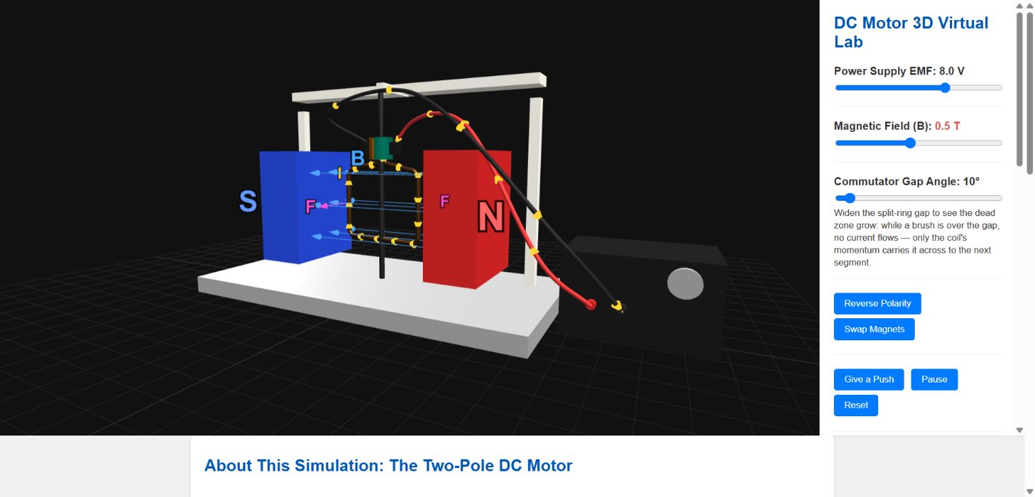
The coil turns because the model evaluates the magnetic force on its current-carrying sides at the coil's instantaneous orientation. The two forces form a couple. The split-ring commutator reverses the coil current every half turn so that the torque continues in the same rotational sense.
The force on each active coil side follows the current and magnetic-field directions.
Reverse only the power-supply polarity and the rotation reverses. Swap only the magnets and it reverses again. Reverse both and the original turning direction returns. These predictions can be tested at any frozen instant using Fleming's left-hand rule.
See a real commutator dead spot
The orange and green split-ring segments rotate with the coil. When a brush crosses an insulating gap, current becomes zero and the force arrows disappear. The coil must coast through that interval using rotational inertia. If it stops in the dead zone, the motor cannot self-start; the Give a Push control reproduces the nudge used with a bench motor.
Back-EMF emerges as the motor accelerates
The current is calculated from I = (V − εback)/R. As the coil spins faster, it generates a larger back-EMF opposing the supply, so the ammeter reading falls. The motor is simultaneously acting as a generator.
Investigate the live model
- Set the supply to 8 V and use Give a Push if the coil begins at the dead spot.
- Pause the model and use the displayed I and B directions to predict each force.
- Reverse the polarity, then reset and swap the magnets.
- Reverse both quantities and explain the resulting direction.
- Widen the commutator gap and compare the current-free coasting interval.
- Watch the current and back-EMF readings during spin-up.
Questions for learners
Downloads and open learning
Made by lookang and created using Claude Fable 5 for Open Educational Resources / Open Source Physics @ Singapore. The packages are self-contained and use local Three.js files, so the simulation can run offline.