Why the “simplest motor” deserves a 3D view
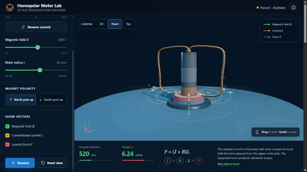
A homopolar motor has no commutator and no wound armature. The wire touches one terminal of the battery and the edge of the magnet, closing a low-resistance circuit. Current then passes through a region where the magnet's field has a strong radial component. The resulting magnetic force is tangential, so the wire experiences a turning effect around the battery's axis.
A flat diagram can hide the key idea: current, field and force point in three different directions. Rotation only becomes intuitive when the learner can orbit the model, follow the current around the real circuit and inspect the vectors at the contact region.
The magnetic field is a loop, not a spray of arrows
Magnetic field lines never begin or end in empty space. For a cylindrical magnet, they emerge from the north face, bow outward through the surrounding space and return into the south face. Inside the magnet, the loop continues from south to north. The simulation therefore uses smooth, rounded field lines instead of isolated radial arrows.
Near the rim of the magnet—the region in which current enters or leaves the conducting wire—the field has an important radial component. That local field direction is what participates in the force calculation. The complete loops show the global field; the B vector near the contact point shows the local field used for the motor effect.
From force to torque
The magnetic force does not simply push the wire away from the magnet. Its direction is tangential around the vertical axis. Because the line of action is offset from the axis, the force produces a torque. A useful simplified relationship is:
Real motors are also affected by contact resistance, wire stiffness, friction, heating and the detailed shape of the field. The simulation intentionally isolates the electromagnetic relationships so that students can test cause and effect before discussing those real-world limitations.
Try the investigation
- Turn on one overlay at a time. Trace the current path, then inspect the rounded magnetic field loops.
- Show I, B and F together near the contact region. Orbit the camera until their three-dimensional relationship is clear.
- Reverse the current. Predict the rotation direction before pressing Run.
- Restore the current and reverse the magnet polarity. Compare the result.
- Reverse both current and polarity. Explain why the rotation direction returns to the original direction.
Five questions for students
A useful classroom misconception check
Ask students whether the magnetic field is “radially outward everywhere.” The better answer is no. The field forms closed loops from north to south outside the magnet, but close to the magnet's edge a radial component can dominate. The motor responds to that local component. The 3D view lets students reconcile the global field-line picture with the local vector used in the force rule.
Credits and open learning
This original interactive and article were made by lookang for Open Educational Resources / Open Source Physics @ Singapore. The visual concept was informed by the physical homopolar-motor arrangement described by JavaLab; no source code or page layout was copied.
Download the complete ZIP package for offline use, classroom sharing or adaptation.
For more interactive learning resources, visit iwant2study.org and the OSPSG electromagnetism collection.