Exercise 1: Introductory Problem
Consider the network of resistors and batteries shown in the first figure below.
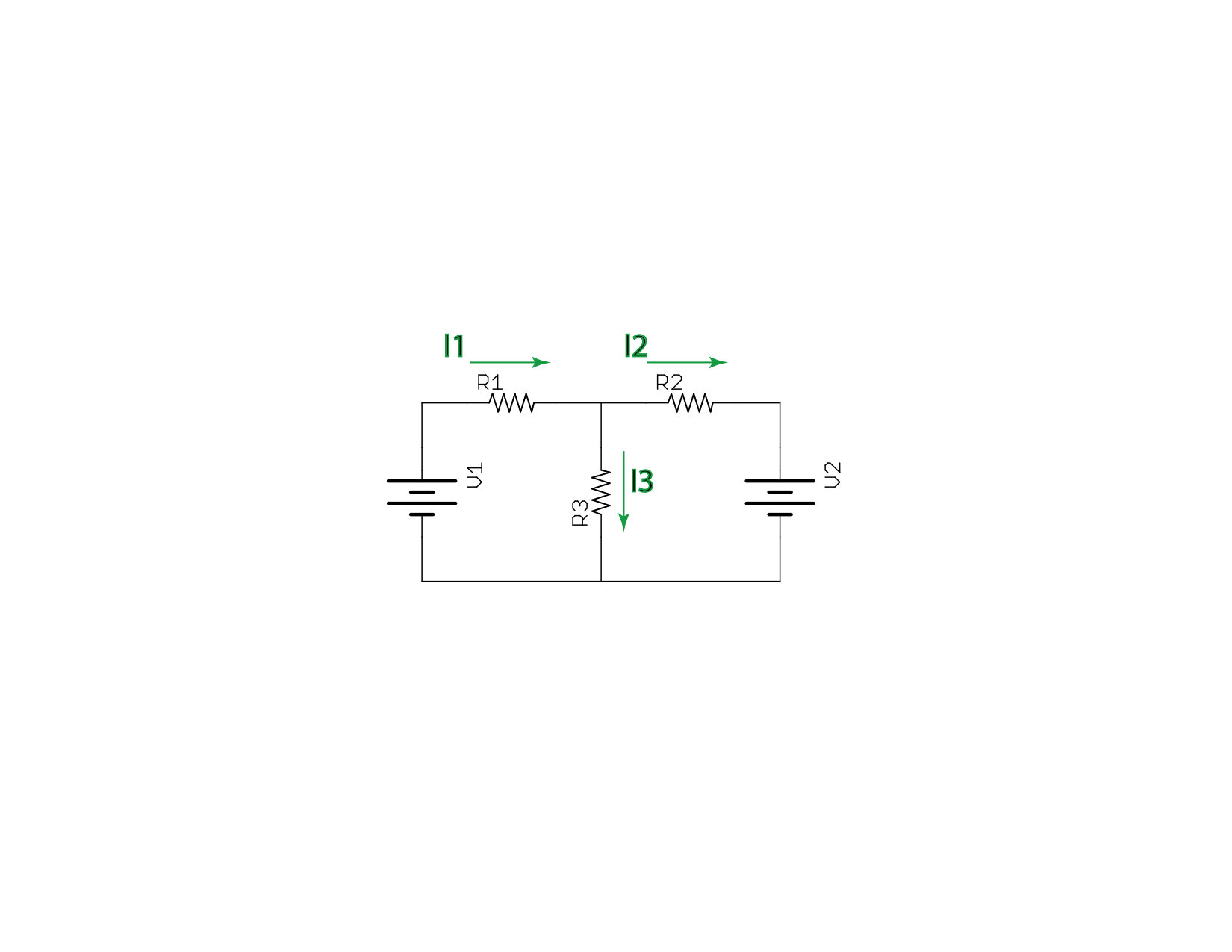
There are three unknowns in that circuit, I1, I2, and I3. We can solve for these unknowns by building a system of equations using Kirchhoff’s Laws:
- The sum of voltages around any loop is zero.
- The sum of currents at any junction is zero.
Applying the voltage law to the left-hand loop, we get
V1−I1R1−I3R3=0(4)
From the right-hand loop, we get
V2+I2R2−I3R3=0(5)
We need one more equation, for which we can use the junction at top center and the current law:
I1−I2−I3=0(6)
We now have the requisite three independent equations, which we can solve using methods learned in high-school algebra.
There’s another way of solving this, using matrix methods. First, rewrite the equations just a bit.
R1I1+0I3+R3I3 0I1−R2I2+R3I3 I1−I2−I3===V1V20(7)(8)(9)
And now we can see that this can be written as a matrix equation!
⎡⎣⎢R1 0 10−R2−1R3R3−1⎤⎦⎥⎡⎣⎢I1 I2 I3⎤⎦⎥=⎡⎣⎢V1 V2 0⎤⎦⎥(10)
This matrix equation,
Mx=b(11)
has solution
x=M−1b(12)
where M−1 is the inverse of M. Most computational packages have built-in capability for inverting matrices.
ASSIGNMENT
- By carrying out the matrix multiplication explicitly, show that the matrix equation above reduces to the system of equations from which it is derived.
- Use a matrix-solving package to find the currents.
- Check your answers by substituting the currents into the equations and verifying that they are solutions.
Exercise 2: More complicated problem
The resistor network below is perhaps a bit more challenging.
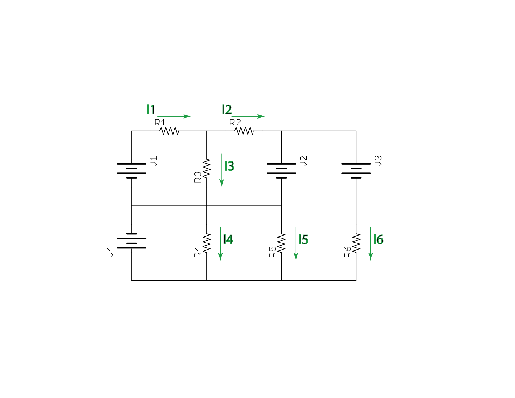
ASSIGNMENT
- Write a system of equations that can be used to solve for the currents in the circuit above.
- Re-write the system of equations from part 1 of this assignment as a matrix equation.
- Use a matrix-solving package to find the currents.
- Check your answers: do the values of currents you found solve the equations with which you started?
- You may notice something interesting if you compare your solution here to your solution for exercise 1. (Assuming the same values of R and V were used in both exercises.) Explain why this happened.
Unless your instructor provides you with other values, assume each voltage source and each resistor has a value 10× its identifying number. (i.e. V2=20 V, R3=30Ω.)