updated 9 January 2017
 |
| refined look |
updated 7 june 2016
 |
Micrometer JavaScript HTML5 Applet Simulation Model by Fu-Kwun Hwang & Loo Kang Wee |
updated 03 july2015. new JavaScript Model available
 |
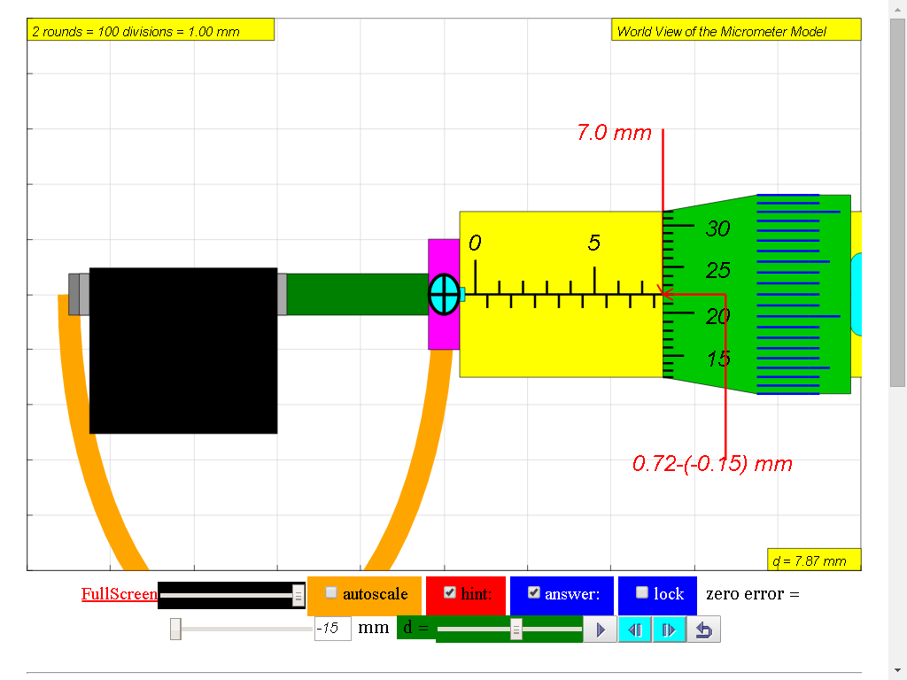
| can you read the reading of the Micrometer? EJSS Micrometer Model http://weelookang.blogspot.sg/2015/07/ejss-micrometer-model.html run: Link1 , Link2 download: Link1, Link2 source: Link1, Link2 |
Ejs open source Micrometer java applet with objects, help & zero error logic
 |
| added ability to magnify and a randomize object width http://weelookang.blogspot.sg/2010/06/ejs-open-source-micrometer-java-applet.html https://dl.dropboxusercontent.com/u/44365627/lookangEJSS/export/ejs_model_Micrometer02.jar https://dl.dropbox.com/u/44365627/lookangEJSworkspace/export/ejs_Micrometer02.jar authors: Fu-Kwun and lookang and wolfgang |
 |
| 08May 2011 version of micrometer simulation http://www.phy.ntnu.edu.tw/ntnujava/index.php?topic=567.msg1944.0 |
Youtube: http://youtu.be/YAmn-xksu2s Micrometer Learning How to Use the Micrometer Through Open Source Physics Java Simulation
alternative host:
http://www.compadre.org/OSP/items/detail.cfm?ID=9422
Full screen applet
kindly hosted in NTNUJAVA Virtual Physics Laboratory by Professor Fu-Kwun Hwang
http://www.phy.ntnu.edu.tw/ntnujava/index.php?topic=683.0
alternatively, go direct to http://www.phy.ntnu.edu.tw/ntnujava/index.php?board=28.0
Collaborative Community of EJS (Moderator: lookang) and register , login and download all of them for free :)
Author: lookang and Fu-Kwun
Original Source code by Fu-Kwun Hwang http://www.phy.ntnu.edu.tw/ntnujava/index.php?topic=567.msg2364#msg2364 Derived work by Wee Loo Kang under creative commons http://creativecommons.org/licenses/by/2.5/tw/deed.en
http://www.phy.ntnu.edu.tw/ntnujava/index.php?topic=683.0
Micrometer Model
Micrometers use the principle of a screw to amplify small distances that are too small to measure directly into large rotations of the screw that are big enough to read from a scale. The accuracy of a micrometer derives from the accuracy of the thread form that is at its heart. The basic operating principles of a micrometer are as follows:The amount of rotation of an accurately made screw can be directly and precisely correlated to a certain amount of axial movement (and vice-versa), through the constant known as the screw's lead. A screw's lead is the distance it moves forward axially with one complete turn (360°). (In most threads [that is, in all single-start threads], lead and pitch refer to essentially the same concept.)
With an appropriate lead and major diameter of the screw, a given amount of axial movement will be amplified in the resulting circumferential movement.
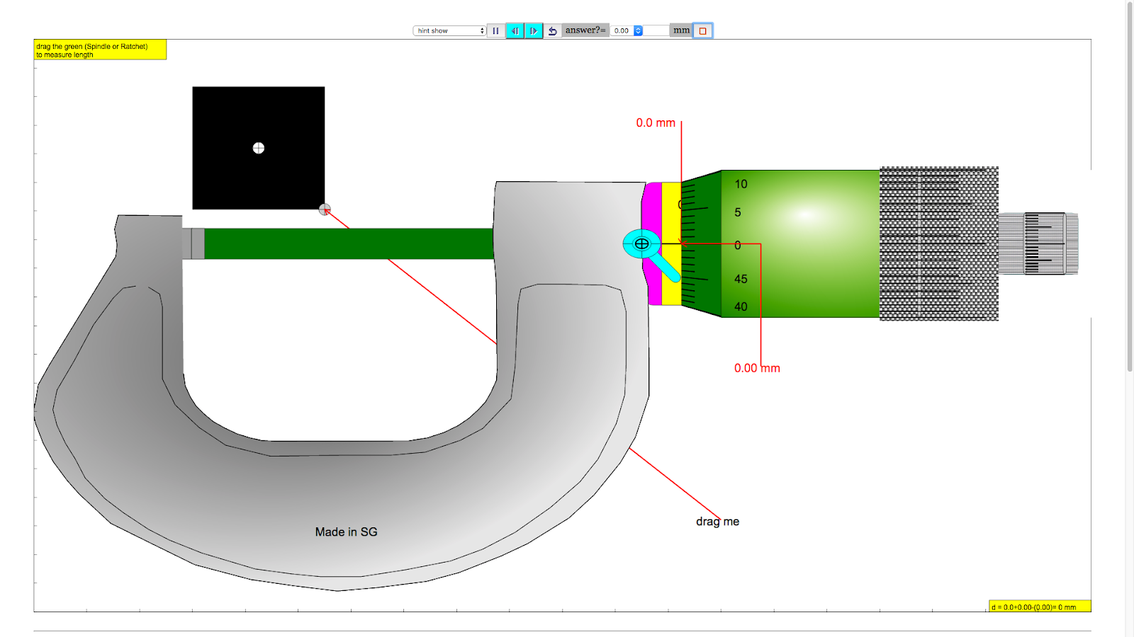
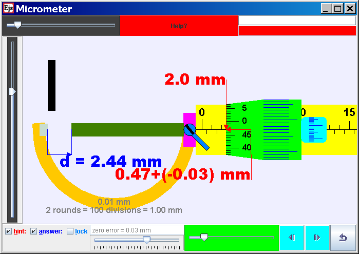
The micrometer has most functional physical parts of a real micrometer.
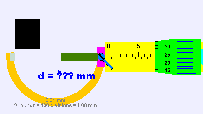
- Frame (Orange) The C-shaped body that holds the anvil and barrel in constant relation to each other. It is thick because it needs to minimize expansion, and contraction, which would distort the measurement. The frame is heavy and consequently has a high thermal mass, to prevent substantial heating up by the holding hand/fingers. has a text 0.01 mm for smallest division of instrument has a text 2 rounds = 100 = 1.00 mm to allow association to actual micrometer
- Anvil (Gray) The shiny part that the spindle moves toward, and that the sample rests against.
- Sleeve / barrel / stock (Yellow) The stationary round part with the linear scale on it. Sometimes vernier markings.
- Lock nut / lock-ring / thimble lock (Blue) The knurled part (or lever) that one can tighten to hold the spindle stationary, such as when momentarily holding a measurement.
- Screw (not seen) The heart of the micrometer It is inside the barrel.
- Spindle (Dark Green) The shiny cylindrical part that the thimble causes to move toward the anvil.
- Thimble (Green) The part that one's thumb turns. Graduated markings.
- Ratchet (Teal) (not shown ) Device on end of handle that limits applied pressure by slipping at a calibrated torque.
This applet has
- an object (Black) with slider on left top to control the y-motion of the object into the anvil and spindle (jaws), the graphics also allows drag action.
- with slider on left bottom to control the x-size of the object into the anvil and spindle (jaws).
- On the left bottom slider is the zero error control to allow of exploring with if the micrometer has either +0.15 mm (max) or -0.15mm (min) zero error.
- The are check boxes:hint: guide lines and arrows to indicate the region of interest plus the accompanying rationale for the answer.
- answer: shows the measurement d = ??? mm
- lock: allows simulating of the lock function in real micrometer which disable changes to the position of the spindle then by the measurement is unchangeable.
- On the bottom there is a green slider to control the position of the spindle, drag on any part of the view also drags the spindle.
- There is 2 buttons left and right fine control to allow for single incremental change of the measurement, to allow learners to sense the rotation simulation of the spindle with the many lines to simulate the coarse pattern to increase friction between fingers and on the thimble and ratchet.
- The reset button restores learning environment to default setting.

http://commons.wikimedia.org/wiki/File:Micrometer_applet.gif
By Lookang (Own work) [CC-BY-3.0 (www.creativecommons.org/licenses/by/3.0)], via Wikimedia Commons
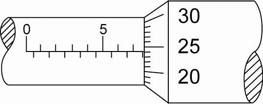
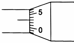
Q1: What is the micrometer reading shown in the diagram?
or
(a) 5.25
(b) 7.24
(c) 7.74
(d) 8.24
(e) 8.74

=main scale + dial scale - (zero error)
=7.50 + 0.24 - ( 0.00)
= 7.74 mm
move the simulation at the top to experience the physics of micrometer
(a) 0.00 mm
(b) 0.01 mm
(c) 0.3 mm
(d) 0.03 mm
(e) 5 mm
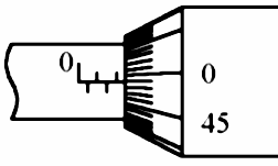
Q3: what is the correct reading on the micrometer given it has a zero error of +0.03 mm?
or

(a) 2.02
(b) 2.41
(c) 2.44
(d) 2.47
(e) 2.52
the answer is
=main scale + micro scale - (zero error)
=2.00 + 0.47 - ( 0.03)
= 2.44 mm
play with the simulation model of the micrometer to experience the physics!
answer key:
Q1: the answer is (c). 7.74 mm
Q2: the answer is (d). 0.03 mm
Q3: the answer is (c). 2.44 mm
animated gif of micrometer with zero error = -0.09 mm. the correct way to use it is =main scale + micro scale - (zero error) = 4.00 + 0.05 - (-0.09) = 4.14 mm
animated gif of micrometer with zero error = +0.15 mm. the correct way to use it is =main scale + micro scale - (zero error) = 4.00 + 0.29 - (0.15) = 4.14 mm

animated gif of micrometer with zero error = 0.00 mm. the correct way to use it is =main scale + micro scale - (zero error) = 4.00 + 0.25 - (0.00) = 4.25 mm
animated gif of micrometer with zero error = 0.00 mm. the correct way to use it is =main scale + micro scale - (zero error) = 4.00 + 0.14 - (0.00) = 4.14 mm
added to Wikipedia! to advance the learning of physics for everyone :)
| Thumbnail | Name | User | Size | Description | |
|---|---|---|---|---|---|
 | 09:27, 20 July 2011 | Micrometernozeroerrornegative0.09mm.gif (file) | Lookang | 88 KB | |
 | 09:27, 20 July 2011 | Micrometer zero error 0.15mm.gif (file) | Lookang | 79 KB | |
 | 09:06, 20 July 2011 | Micrometer no zero error 4.25 mm.gif (file) | Lookang | 167 KB | (2 frame per sec to get animated thumbnail) |
 | 09:05, 20 July 2011 | Micrometer no zero error.gif (file) | Lookang | 19 KB | (Reverted to version as of 07:33, 20 July 2011 animated) |
changes made:
This is an Ejs version of micrometer with1. option for positive or negative zero error for faulty micrometer(Adjust the vertical slider up/down).
2. option for object black color to be inserted for measurement
3. option for hint to display
4. option for answer to display
5. option fine control for ratchet
6. a lock to store the value of measurement like in a real micrometer so that you can ask others to look at the reading too without having the object inside. Smiley
7. moved the object to the foreground to achieve the no over squeezed look by the spindle
8. added threads on green dial and ratchet to give it the rotating look
9. lock can be press on graphically
10. at the moment, the ratchet can be compress by extra mm to demonstrate materials can be measured inaccuracy if over rotated by students against the anvil, which is somewhat inaccurate but i think there is educational value if the applet can over compress ? to get the correct measurement, drag on the slider for thimble
11. made black object do not overlap the micrometer, suggested by Ered
12. made hint for zero error case make clear the impact of new calculation
13. re position (lower and in screen) the hint for the 0.00 mm for even measurements like 13.77 mm
14. updated now with lock and ratchet buttons for fine control on 08 Feb 2009
15. updated now with suggestion from Ered on 10 Feb 2009
07September 2009
16 black object is blocked (simulate real life object blocking) if the micrometer jaws is too small.
17) micrometer jaw to become smaller than the block.?
18 improved documented variables in the variable tables.
19. drawing object redesign in EJs4.2 format
20. new rotation ratchet implemented by prof wolfgang to simulate real life action of rotation of ratchet instead of slider bar in previous versions.
11Sept 2009
21 zero error = 0.05 mm instead of e = 5 display
22 redeploy thimble slider
23 reposition the object slider to top
24 correct spelling
19Nov2009
25 added the input text field for checking of understanding by the students thx to Prof Hwang expert guidance http://www.phy.ntnu.edu.tw/ntnujava/index.php?topic=1309.0
8may2011
added tips o the jaws
add ability of drag up and down on the green spindle and teal ratchet to move the micrometer to simulate almost like moving the parts like in real equipment.
20july 2011
added ability to zoom in to focus on the parts of the micrometer to look at when measuring length
made the text black to increase visibility due to editable=false is a shade of gray and not very clear
21july 2011
added correct sign fig for example 9.20 = 9.00+0.20 mm extra 0 at the back using logic and code to make 0 appear
improved 9.20 = 9.00+0.10-(-0.10) mm adding extra 0 at the right else if branch. previously it shown 9.20 = 9.0 + 0.1-(-0.1) mm
24 October 2011
added a magnify ability to draw students attention to the lines based on codes from http://www.phy.ntnu.edu.tw/ntnujava/index.php?topic=2268.0 by Fu-Kwun Hwang
randomize the size of the black object each time to simulation is reset based on a request on physics front http://www.thephysicsfront.org/items/detail.cfm?ID=9422
Thanks to Prof Hwang for sharing his original source codes, his passion for sharing knowledge and guidance .
This work is licensed under a Creative Commons Attribution 2.5 Taiwan License.
reference:
reference:
http://www.phy.ntnu.edu.tw/ntnujava/index.php?topic=567.msg1944#msg1944


