


Translations
| Code | Language | Translator | Run | |
|---|---|---|---|---|
 |
||||
Software Requirements
| Android | iOS | Windows | MacOS | |
| with best with | Chrome | Chrome | Chrome | Chrome |
| support full-screen? | Yes. Chrome/Opera No. Firefox/ Samsung Internet | Not yet | Yes | Yes |
| cannot work on | some mobile browser that don't understand JavaScript such as..... | cannot work on Internet Explorer 9 and below |
Credits

 Fu-Kwun Hwang; Loo Kang Wee
Apps
![]()
Sample Learning Goals
Description
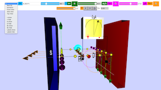
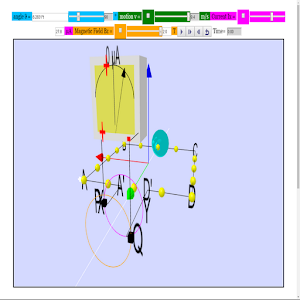
Electric generators turn motion into alternating-current electric power by exploiting electromagnetic induction. This AC generator consists of 2 pole magnets and a wire (usually a very long one that's wrapped to form several coils and known as an armature or coil). A hydraulic engine or some other outside source of motion (This applet has a handle bar for you to rotate) moves the wire or armature through the external magnetic field created by the magnets
When a wire passes through an external magnetic field, it causes electrons in that wire to move together in one direction. The current in the wire produce a magnetic field around the wire. The 2 different magnetic fields interact with each other results in a voltage (emf) to be "induced" in the coil. This motion of the electrons in the loop that is placed in a magnetic field is caused by a motional electromagnetic force (emf).
A simple alternating current (AC) generator is illustrated here. ABCD is mounted on an axle PQ. The ends of the wire of the loop are connected to 2 brushes contacting two slip rings continuously at position X & Y. Two carbon brushes are made to press lightly against the slip rings.
The key to producing motional emf is in change in the magnetic flux experienced by the coil loop.
In the case when an outside handle bar is rotating at θ (t) = 0.5*t, the coil is spinning at a constant rate of angular velocity ω = 0.5 rad/s within an external magnetic field. Because it is always moving through the magnetic field, a current is sustained but always varying. But, because the coil is spinning, it's moving across the magnetic field first in one direction and then in the other, which means that the flow of electrons keeps changing. Because the electrons flow first in one direction and in the other, the generator produces an alternating current.
For Teachers
Faraday's law states the induced emf in a coil is equal to the negative of the rate of change of magnetic flux times the number of turns in the coil. The induced electromotive force or emf, ε in any closed circuit is equal to the rate of change of the magnetic flux , Φ through the circuit.
|ε| = | d(Φ)/ dt |
Where Φ = N.B.A cos ( B&A)
|ε| is the magnitude of the electromotive force (emf) in volts
Φ is the magnetic flux through the circuit (in Weber).
N is the number of turns of wire in the loop
B is the magnetic field
A is area of coil
Angle B&A is the angle between vector magnetic field and vector perpendicular to the area
Lenz's law states an induced current is always in such a direction as to oppose the motion or change causing it.
The law provides a physical interpretation of the choice of sign in Faraday's law of induction, indicating that the induced emf and the change in flux have opposite signs. The the polarity of the induced emf is such that it produces a current whose magnetic field opposes the change which produces it
ε = - d(Φ)/ dt
Apply Faraday's law and Lenz's law to the simulation model:
For the case of a rotating loop,
ε = - d(Φ)/ dt
From earlier equation as Φ = N.B.A cos ( B&A)
ε = - d(N.B.A cos ( B&A))/ dt
The physical setup of Bz and normal vector of area A when t = 0 s, such that angle B&A = ( θ + π/2 ).
And taking out the constants from the differential equation,ε = - N.B.A d( cos ( θ + π/2 )/ dt
From mathematical trigonometry identity, cos ( θ + π/2) = -sin ( θ )
ε = - N.B.A d(-sin ( θ )/ dt
To derive an expression for the induced emf across the slip rings when the coil is spun at an angular frequency, ω, knowing θ = ω.t
ε = - N.B.A d(-sin ( ω.t )/ dt )
ε = N.B.A d( sin ( θ )/ dt ) which the equation used by the custom function getCurrent () = d( sin ( θ )/ dt )
When a closed circuit in connected to the rotating loop, using Ohm's law
ε = N.B.A.d( sin ( θ )/ dt ) = I.R which the equation used by the simulation model
When mechanical energy is used to rotate the loop, the armature induced an emf described by the right hand rule. The induced emf in a coil is equal to the negative of the rate of change of magnetic flux times the number of turns in the coil.
Use the rotating handle function input field θ(t)= _________ to see what happens when the rotating handle cranks the loop in the Bz magnetic field. The checkbox current flow & electron flow allow different visualization since I = d(Q)/dt and Q= number of charge*e. The Play & Pause button allows freezing the 3D view for visualizing these induced currents and for checking for consistency with the right hand rule.
When the rotating handle is moved by the input field θ(t)= 2*t , induced current runs through ABCD (select the checkbox labels?) in a manner described by
ε = N.B.A.ω .cos ( ω.t ) = I.R.
Interpretation of graphs of ε versus t
If θ(t)= 2*t , imply 2 =ω ε/R = N.B.A.ω .cos ( ω.t )/R = I. which is the modeled equation.
If N = 1, B = 2 x10⁻⁶ T, A = 1.5*1.5 m*m, R = 1 Ω
ε/R = 1.2.1.5*1.5.2x10-6 .cos ( 2.t )/1 = I.
ε = 9x10⁻⁶ cos ( 2.t ) = I
Interpretation of graphs of Φ versus t
Since ε = - d(Φ)/ dt
Therefore, 9x10⁻⁶ cos ( 2.t ) = - d(Φ)/ dt
- ∫ 9x10⁻⁶ cos ( 2.t ).dt = (Φ)
- 4.5x10⁻⁶ sin ( 2.t ) = (Φ)
Activity Exercises
Engage:
Question: Given the context of global energy crisis, fossil fuel as primary source of energy and its effects of global warming, are you aware of any alterative energy source?
Possible student responses: Many students probably already know of clean energy and able to verbally mention some of them such as wind and wave energy.
Answer: Yes! Wind energy and wave energy are examples of energy sources that convert mechanical sources of energy and convert it to electrical energy. Later, we will demonstrate a way to convert human mechanical energy in the form of rotating an axle to rotate a coil so as to get electrical energy.
A real live demo is best.
Explore
1. Explore the simulation; this simulation is designed as an electric generator that turns motion into alternating-current electric power by exploiting electromagnetic induction. This AC generator model consists of 2 pole magnets and a wire (usually a very long one that's wrapped to form several coils and known as an armature or coil). A hydraulic engine or some other outside source of motion (This applet has a handle bar for you to rotate) moves the wire or armature through the external magnetic field created by the magnets.
2 The play button runs the simulation, click it again to pause and the reset button brings the simulation back to its original state.
3 by default values Bz, Lengthx, Lengthz, N, R, ϑ = 6.2831*t play the simulation. Notice ϑ = 6.2831*t is the angular displacement function of the handle bar. The wire is in a rotation motion and the galvanometer display the induced current in the AC generator. What is the physics principle simulated here.
Hint: Faraday's law
4 reset the simulation.
5 using the default values (Bz, Lengthx, Lengthz, N, R,), adjust the value of ϑ = 1*t play the simulation. What did you observe? Explain the motion in terms of the ϑ, ω
6 explore the slider Bz. what do this slider control?
7 explore the slider Lengthx. What does this slider control?
8 explore the slider Lengthz. What does this slider control?
9 together a variable called A is defined as Lengthx*Lengthz, suggest a suitable meaning for A.
10 by leaving the cursor on the slider, tips will appear to give a description of the slider. You can try it the following sliders such as the N, R, t, Φ , ε , i, v.
11 record down the names of the variables and its meaning from the tips.
9 there are some value of time of simulation t and the checkbox graph for height vs time.
10 vary the simulation and get a sense of what it does.
11 There is an external magnet with the poles as setup in the z axis direction.
What are the magnetic poles when Bz is positive?
12 What can you conclude about the directions of the magnetic field exerted by the magnets?
hint: the magnetic field vectors comes out from which pole when view from outside the magnet.
13 The external magnetic field Bz can be varied using the slider Bz. When Bz is positive, it is in the direction vertically up. Vary Bz until it is negative, what is the direction of the Bz then?
Evaluate:
14 Input into the input field θ(t) = __6.2832*t___
When θ = 0o What is amount of magnetic flux Φ passing through the area of the coil loop is zero Wb.
15 Step the simulation by dt, take note of the new value of the θ and the new Φ reading. By calculating d(Φ)/ dt, at this instant in time. Think of a way, to collect the data to fill in the following table.
| θ / deg. | t / s | Φ / Wb | d(Φ)/ dt / Wb/s | to be read from the graph ε / V |
i / A |
| 0 | |||||
| 18 | |||||
| 36 | |||||
| 54 | |||||
| 72 | |||||
| 90 | |||||
| 108 | |||||
| 126 | |||||
| 144 | |||||
| 162 | |||||
| 180 | |||||
| 198 | |||||
| 216 | |||||
| 234 | |||||
| 252 | |||||
| 270 | |||||
| 288 | |||||
| 306 | |||||
| 324 | |||||
| 342 |
Select the Checkbox "Show Graph" and record down the value of the emf ε. Suggest a relationship between emf ε and the variables in the table. Collect more data to fill in the table if need.Elaborate:
16 The following passage (just an example) aims to aid learners describe a simple form of a.c. generator (rotating coil or rotating magnet) and the use of slip rings (where needed)When a coil is _______________ between the poles of the ___________, its wires cut through the _______________ causing an induced emf to be generate which causes a ____________ to flow if there is a closed electrical path circuit.
The _________ and ______________ of the induced current _____________ as the coil rotates. This is the basic principle behind the simple AC generator.(c) Sketch a graph of voltage output against time for a simple a.c. generator
Using default starting values of the simulation, play the simulation until at θ = 0 degree again at t > 0.0 s
What is the direction of the current flow in wire AB?
What is the direction of the current flow in wire CD?
using Fleming's left-hand rule, deduce the relative directions of force acting on
i) AB
ii) CD
iii) BC
iv) DA.
Hint: note that Fmag = I*B*L*sin(I&B) may be useful.By taking moments about the axle PQ, consider the forces on AB and CD, deduce the direction of the torque T and the motion if the coil loop was initially at rest (ω = 0 deg/s). Select the suitable sliders of your choice and verify your hypothesis for 2 angles.
Discuss with your partner what you have discovered.
Ask your teacher if there are any problem/issues faced using this virtual lab.Explain and show the equations involving T ( in earlier part of question), why the forces on wire BC and DA did not contribute to the calculation of rotating torque about axle PQ?By considering the forces in the x direction for wire BC and DA, suggest what can happen to the coil loop if the forces are large enough. Suggest why it does not happen in terms of the properties of the wires in the coil loop.Explain how a rotating coil in a magnetic field experiences a change in magnetic flux linkage and the induced emf.
What is the effect on the induced emf by increasing
(i) the number of turns on the coil, N
(ii) the angular velocity, ω
(iii) the magnitude of the external Bz field.
After conducting some inquiry learning and examining the 3D view of the model on the virtual AC generator model discuss how this induced emf can be measured. You may right-click within a plot, and select "Open EJS Model" from the pop-up menu to examine the model equations of the motion. You must, of course, have EJS installed on your computer.Describe the action of the slip rings of the AC generator. Suggest the effect of adding a soft-iron cylinder in the winding the coil.Advanced Learner:
Please submit your remix model that model features that are not available in the existing virtual lab and share your model with the world through NTNUJAVA Virtual Physics Laboratory http://www.phy.ntnu.edu.tw/ntnujava/index.php?board=28.0. Impacting the world with your model now.
Research
[text]
Video
Version:
Other Resources
[text]
end faq
{accordionfaq faqid=accordion4 faqclass="lightnessfaq defaulticon headerbackground headerborder contentbackground contentborder round5"}
- Details
- Parent Category: 05 Electricity and Magnetism
- Category: 09 Electromagnetic Induction
- Hits: 20449