
.png
)


Translations
| Code | Language | Translator | Run | |
|---|---|---|---|---|
 |
||||
Software Requirements
| Android | iOS | Windows | MacOS | |
| with best with | Chrome | Chrome | Chrome | Chrome |
| support full-screen? | Yes. Chrome/Opera No. Firefox/ Samsung Internet | Not yet | Yes | Yes |
| cannot work on | some mobile browser that don't understand JavaScript such as..... | cannot work on Internet Explorer 9 and below |
Credits

 Fu-Kwun Hwang - Dept. of Physics, National Taiwan Normal Univ.; lookang (This email address is being protected from spambots. You need JavaScript enabled to view it.)
end faq
Apps
![]()
https://itunes.apple.com/us/app/dc-motor-3d-simulator/id1162611119?ls=1&mt=8
Sample Learning Goals
O level Syllabus
This helps students learn
explain how a current-carrying coil in a magnetic field experiences a turning effect and that the effect is increased by increasing
(i) the number of turns on the coil,
(ii) the current
discuss how this turning effect is used in the action of an electric motor
describe the action of a split-ring commutator in a two-pole, single-coil motor and the effect of winding the coil on to a soft-iron cylinder
UPPER SEC SCIENCE PHYSICS (EXP/5NA) (2013) (2013)
(j) deduce the relative directions of force, field and current when any two of these quantities are at right angles to each other using Fleming's left-hand rule
(k) explain how a current-carrying coil in a magnetic field experiences a turning effect (recall of structure of an electric motor is not required)
Exercises:
The external magnetic field Bz can be varied using the slider Bz. When Bz is positive, it is in the direction vertically up. Vary Bz until it is negative, what is the direction of the Bz then?
The current comes from the battery higher potential end and travels in a wire forming a closed circuit and travels back to the lower potential end of the battery. When θ = 0o current flows from the battery higher potential end, to the top brush, to the RED split ring, through the coil loop in order ABCD, back to BLUE split ring, bottom brush and lower potential end of the battery. What is the direction of the current flow in wire AB? What is the direction of the current flow in wire CD? using Fleming's left-hand rule, deduce the relative directions of force acting on i) AB ii) CD iii) BC iv) DA. hint: note that Fmag = I*B*L*sin(I&B) may be useful.
By taking moments about the axle PQ, consider the forces on AB and CD, deduce the direction of the torque and the motion if the coil loop was initially at rest (ω = 0 deg/s). Select the suitable sliders of your choice and verify your hypothesis for 2 angles. Discuss with your partner what you have discovered. Ask your teacher if there are any problem/issues faced using this virtual lab.
Explain and show the equations involving T ( in earlier part of question), why the forces on wire BC and DA did not contribute to the calculation of rotating torque about axle PQ?
By considering the forces in the x direction for wire BC and DA, suggest what can happen to the coil loop if the forces are large enough. Suggest why it does not happen in terms of the properties of the wires in the coil loop.
Explain how a current-carrying coil in a magnetic field experiences a turning effect and that the effect is increased by increasing (i) the number of turns on the coil, (ii) the current (iii) increasing the magnitude of the external Bz field
After conducting some inquiry learning on the virtual DC motor model discuss how this turning effect is used in allowing the coil loop to rotate. You may right-click within a plot, and select "Open EJS Model" from the pop-up menu to examine the model equations of the motion. You must, of course, have EJS installed on your computer.
Describe the action of a split-ring commutator in a two-pole magnet setup, single-coil motor. Suggest the effect adding a soft-iron cylinder in the winding the coil.
Advanced Learner:
Please submit your remix model that model features that are not available in the existing virtual lab and share your model with the world through NTNUJAVA Virtual Physics Laboratory http://www.phy.ntnu.edu.tw/ntnujava/index.php?board=28.0. Impacting the world with your model today!
For Teachers
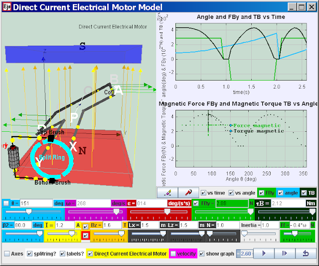
Direct Current Electrical Motor Model
Electric motors turn electricity into motion by exploiting electromagnetic induction. A current-carrying loop that is placed in a magnetic field experiences a turning effect.A simple direct current (DC) motor is illustrated here. ABCD is mounted on an axle PQ. The ends of the wire are connected to a split ring commutator at position X & Y. The commutator rotates with the loop. Two carbon brushes are made to press lightly against the commutators.
The motor features a external magnet (called the stator because it’s fixed in place) and an turning coil of wire called an armature ( rotor or coil, because it rotates). The armature, carrying current provided by the battery, is an electromagnet, because a current-carrying wire generates a magnetic field; invisible magnetic field lines are circulating all around the wire of the armature.
The key to producing motion is positioning the electromagnet within the magnetic field of the permanent magnet (its field runs from its north to south poles). The armature experiences a force described by the left hand rule. This interplay of magnetic fields and moving charged particles (the electrons in the current) results in the magnetic force (depicted by the green arrows) that makes the armature spin because of the torque. Use the slider current I to see what happens when the flow of current is reversed. The checkbox current flow & electron flow alows different visualization since I = d(Q)/dt and Q= number of charge*e. The Play & Pause button allows freezing the 3D view for visualizing these forces, for checking for consistency with the left hand rule .
Introduction
the following case describe a postive current i, postive B field, θ start = 90o , split-ring commutator gap β2= 80o
The split-ring commutator allows electricity flows from the positive terminal of the battery through the circuit, passes through a copper brush [rectangle black boxes] to the commutator, then to the armature.
Postive current runs through ABCD as shown in the diagram (select the checkbox labels?), a +y direction force would act on AB. An -y direction force would act on CD. Taking moments about the axle conveniently, reveals a resultant torque T = Fmag*AD*cosθ acts on the coil loop. The coil loop rotates in an clockwise manner (view from battery side) starting 90o until it reaches the θ = 170o position (assuming that split ring angle are default at β2 = 80o). At this θ = 170+o position, the current is cut off. However, the momentum of the loop carries it past the horizontal position until the coil loop reaches θ = 190o position. Contact between loop and split ring commutator is established again and the current in the coil loop is now reversed (note that current i is still positive). A -y direction force now acts on AB while a +y direction force acts on CD. The rotation motion is reinforced clockwise (view from battery side) as θ continues to rotate from 190o to 350o. At this θ = 350+o position, the current is cut off. However, the momentum of the loop carries it past the verticall position until the coil loop reaches θ = 10o position. Contact between loop and split ring commutator is established again and the current in the coil loop is now reversed back to same as at θ = 90o. A a +y direction force would act on AB. An -y direction force would act on CD and the loop reaches θ = 90o . The cycle repeats after θ = 90o allowing the armature to experience torque in the reinforced direction at the right time to keep it spinning.
Function of split-ring commutator:
The purpose of the commutator is to reverses the direction of the current in the loop ABCD for every half a cycle.
A swing back and fro motion (maybe θ = 90o increase to 270o and decrease back to 90o) is all you would get out of this motor if it weren't for the split-ring commutator — the circular metal device split into parts (shown here in teal with a gap of β2) that connects the armature to the circuit.
In other words
A electric motor is a device for transforming electrical energy into mechanical energy; an electric generator does the reverse, using mechanical energy to generate electricity. At the heart of both motors and generators is a wire coil in a magnetic field. In fact, the same device can be used as a motor or a generator.
When the device is used as a motor, a current is passed through the coil. The interaction of the magnetic field with the current causes the coil to spin. To use the device as a generator, the coil is spun, inducing a current in the coil.
Let's say we spin a coil of N turns and area A at a constant rate in a uniform magnetic field B. By Faraday's law, the induced emf is given by:
ε = -N d(BA cos(Φ))/dt
B and A are constants, and if the angular speed w of the loop is constant the angle is:
θ = wt
The induced emf is then:
ε = -NBA d(cos(wt))/dt = wNBA sin(wt) = εo sin(wt)
Spinning a loop in a magnetic field at a constant rate is an easy way to generate sinusoidally oscillating voltage...in other words, to generate AC electricity. The amplitude of the voltage is:
εo = wNBA
In North America, AC electricity from a wall socket has a frequency of 60 Hz. but in Singapore is 50 Hz The angular frequency of coils or magnets where the electricity is generated is therefore 60 Hz in USA or 50 Hz in Singapore.
To generate DC electricity, use the same kind of split-ring commutator used in a DC motor to ensure the polarity of the voltage is always the same. In a very simple DC generator with a single rotating loop, the voltage level would constantly fluctuate. The voltage from many loops (out of synch with each other) is usually added together to obtain a relatively steady voltage.
Rather than using a spinning coil in a constant magnetic field, another way to utilize electromagnetic induction is to keep the coil stationary and to spin permanent magnets (providing the magnetic field and flux) around the coil. A good example of this is the way power is generated, such as at a hydro-electric power plant. The energy of falling water is used to spin permanent magnets around a fixed loop, producing AC power.
Research
on an eariler Java version
ollection of photo taken by Kai Suah on a pilot lesson April 29th 2011 to test the worksheet and simulation, thanks bro!


Notes from Boon Chien

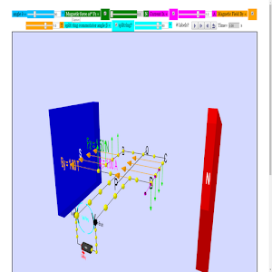
by using these 2 simulations separately, it is possible to achieve the look in the notes.
- Direct Current Motor or DC motor in 3D WebGL JavaScript HTML5 Applet Simulation Model by Fu-Kwun Hwang and Loo Kang Wee
- Magnetic Field of 2 current conducting wires JavaScript HTML5 Applet Simulation Model by Fu-Kwun Hwang and Loo Kang Wee
thus, i will not force the 2 simulations together as the handphone display cannot be optimised with 2 such layouts.
Use alternate Tab in your chrome browser, to play both both simulations!
Video
-
Electromagnetism (part 1): Force acting on a current-carrying conductor in a magnetic field by ETDtogo
-
Electromagnetism (part 2): Working Principles of a DC Motor by ETDtogo https://www.youtube.com/watch?v=e1Uz3Dcav-g
- https://www.youtube.com/watch?v=w4tSAuhnw2E Electromagnetism (part 3): Function of a Split Ring by ETDtogo
- http://youtu.be/t4qBcVSyVT0 Ejs Open Source Direct Current Electrical Motor Model
- http://www.aps.org/programs/education/teachers/teachers-days/presentations/upload/090819-DC-motor-annotated-web.pdf Watch physicists Becky Thompson-Flagg and Ted Hodapp trade quips as they show how to take apart a small DC motor and find out how it works. They get the armature of the motor spinning with just a battery, a few wires, and a permanent magnet. The experiment in this video is the same one described in the DC Motor Annotated Activity Handout.
ICT Connection
- http://library.opal.moe.edu.sg/ictc&func=view&rid=2050 Boon Chien Yap
- http://library.opal.moe.edu.sg/ictc&func=edit&rid=135 by Sim Kah Suan
Worksheets
-
http://iwant2study.org/lookangejss/05electricitynmagnetism_22electromagneticinduction/ejs/ejs_model_DCmotor10.doc Worksheet by Loo Kang Wee
-
EM DC motor (2)Worksheet.pdf Worksheet by Boon Chien Yap
-
EM DC motor (AST_SSC_ETD) Worksheet.doc by Boon Chien Yap
-
Electromagnetism DC Motor Lesson Plan(AST_SSC_ETD).doc by Boon Chien Yap
Version:
- http://weelookang.blogspot.sg/2016/06/ejs-open-source-direct-current.html
- http://weelookang.blogspot.sg/2013/07/dc-motor-explained.html
- https://iwant2study.org/ospsgx/index.php/interactive-resources/physics/05-electricity-and-magnetism/08-electromagnetism/313-ejs-model-dcmotor10
- http://iwant2study.org/lookangejss/05electricitynmagnetism_22electromagneticinduction/ejs/ejs_model_DCmotor10.jar Standby Jar files for computers
-
http://weelookang.blogspot.sg/2010/06/ejs-open-source-direct-current.html
Ejs Open Source Direct Current Electrical Motor Model Java Applet ( DC Motor ) « on: October 23, 2009, 06:14:56 PM » posted from:Singapore,,Singapore author: fu-kwun hwang and lookang
https://dl.dropboxusercontent.com/u/44365627/lookangEJSS/export/ejs_model_DCmotor10.jar
https://dl.dropboxusercontent.com/u/44365627/lookangEJSworkspace/export/ejs_users_sgeducation_lookang_DCmotor10.jar - http://iwant2study.org/lookangejss/05electricitynmagnetism_22electromagneticinduction/ejs/ejs_model_DCmotor10.jarby Fu-Kwun Hwang and Loo Kang Wee Java version from Digital Library
- http://physci.kennesaw.edu/mzoughi/Simulations.shtm using this model too http://physci.kennesaw.edu/ejs/ejs_TM_NTNU_DCmotor.jar Taha Mzoughi's implementation of the torque looks ok but i don't understand why his model the inertia of the DC motor affects the magnetic force.
- http://www.phy.ntnu.edu.tw/ntnujava/index.php?topic=1266.0 by Fu-Kwun Hwang and Loo Kang Wee Java version from NTNU Virtual Lab
- http://www.phy.ntnu.edu.tw/ntnujava/index.php?topic=912.0 by Fu-Kwun Hwang original Java version
- http://weelookang.blogspot.sg/2011/05/physics-on-shoestring-pop-up-electric.html
Other Resources
- https://vle.learning.moe.edu.sg/community-gallery/lesson/edit/84a42ae3-9fe4-4654-9cc1-f41810d9ee93
- https://www.geogebra.org/m/PN2YrxBb DC Motor by ukukuku
- Physics on a Shoestring: A pop-up electric motor by Martin Monk 2003 Phys. Educ. 38 61 doi: 10.1088/0031-9120/38/1/404http://iopscience.iop.org/0031-9120/38/1/404
so this is how is looks like! adapted from Physics on a Shoestring: A pop-up electric motor by Martin Monk 2003 Phys. Educ. 38 61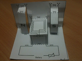

Credits
Fu-Kwun Hwang and Loo Kang Wee
end faq
